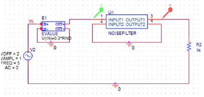


Observe the simulation results (traces of signals) in OrCAD PSpice A/D Demo. Setup analysis to tell SPICE what simulation you need (transient analysis, DC sweep, etc.) 4. Define the SPICE model for NMOS and PMOS transistors. Set the values for all the parts, for example, the resistance values of resistors, the width (W) and length (L) of transistor, etc. Mark the nodes you are interested in with labels. Make the necessary rotations for the parts, and move the parts to appropriate locations. First insert all the parts without considering their values (for example, place a resistor without considering the resistance value of it, etc.). This can be divided into following substeps. We perform PSPICE schematics circuit simulation according to following steps: 1. In the analysis we will find the I D current and the V DS voltage at the given values of V DD and V GS. The circuit diagram below is what you will build in PSPICE. Xiong This tutorial will guide you through the creation and analysis of a simple MOSFET circuit in PSPICE Schematic. 1 PSPICE Schematic Student 9.1 Tutorial -X.


 0 kommentar(er)
